Encoder-Based PID Motor Control
Project Overview
A closed-loop motor control system using quadrature encoder feedback and a classic PID controller. Gains were tuned empirically to trade off overshoot, settling time and steady-state error.
An open-loop PWM drive cannot hold position or velocity under load. A feedback controller is required to reject disturbances and track a reference reliably.
- ›Read a quadrature encoder in interrupts without missing counts
- ›Implement proportional, integral and derivative terms in embedded C
- ›Tune Kp, Ki, Kd for a stable response with minimal overshoot
- ›Log response data for step-input analysis
System Architecture
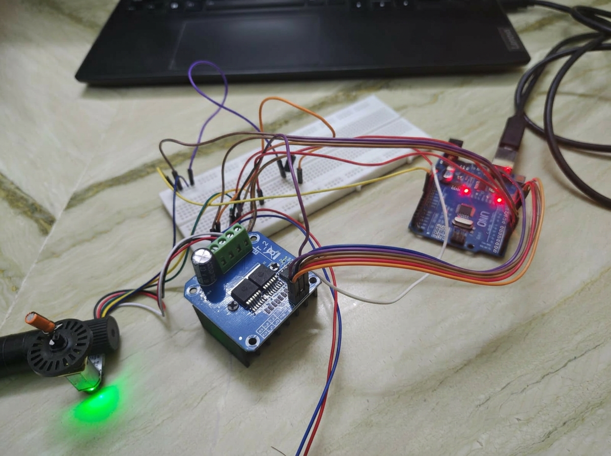
Encoder → interrupt-driven counter → PID loop at fixed sample rate → PWM to H-bridge → motor → back to encoder. A UART link streams reference/measured values for offline plotting.
Error = reference − measured. PID output = Kp·e + Ki·∫e dt + Kd·de/dt, saturated and mapped to a PWM duty cycle.
Hardware Components
- ▹DC motor with quadrature encoder
- ▹H-bridge driver
- ▹Arduino Uno
- ▹Bench PSU + USB-serial link
Software Stack
- ▹Custom PID loop in embedded C
- ▹Interrupt-driven encoder decoding
- ▹Serial logger for step-response capture
Development Journey
Started with P-only to build intuition, added I to eliminate steady-state error, then D to damp overshoot. Retuned after mechanical load changes.
A fixed loop period keeps the discrete PID equations valid and simplifies gain tuning.
The integral term is clamped when the PWM output saturates to prevent windup.
Challenges & Solutions
Moved decoding into a hardware-interrupt ISR and used a compact state-machine decoder.
Added output-saturation-aware integral clamping.
Performance Results
Visuals & Media
Downloads
Improvements & Lessons
- +Auto-tuning via relay feedback (Åström–Hägglund)
- +Cascade position + velocity loops
- +Move implementation to STM32 with hardware timer encoder mode
- ›PID gains are coupled — tune one term at a time and log responses.
- ›Anti-windup matters as much as the gains themselves.