
4-bit R-2R Ladder DAC
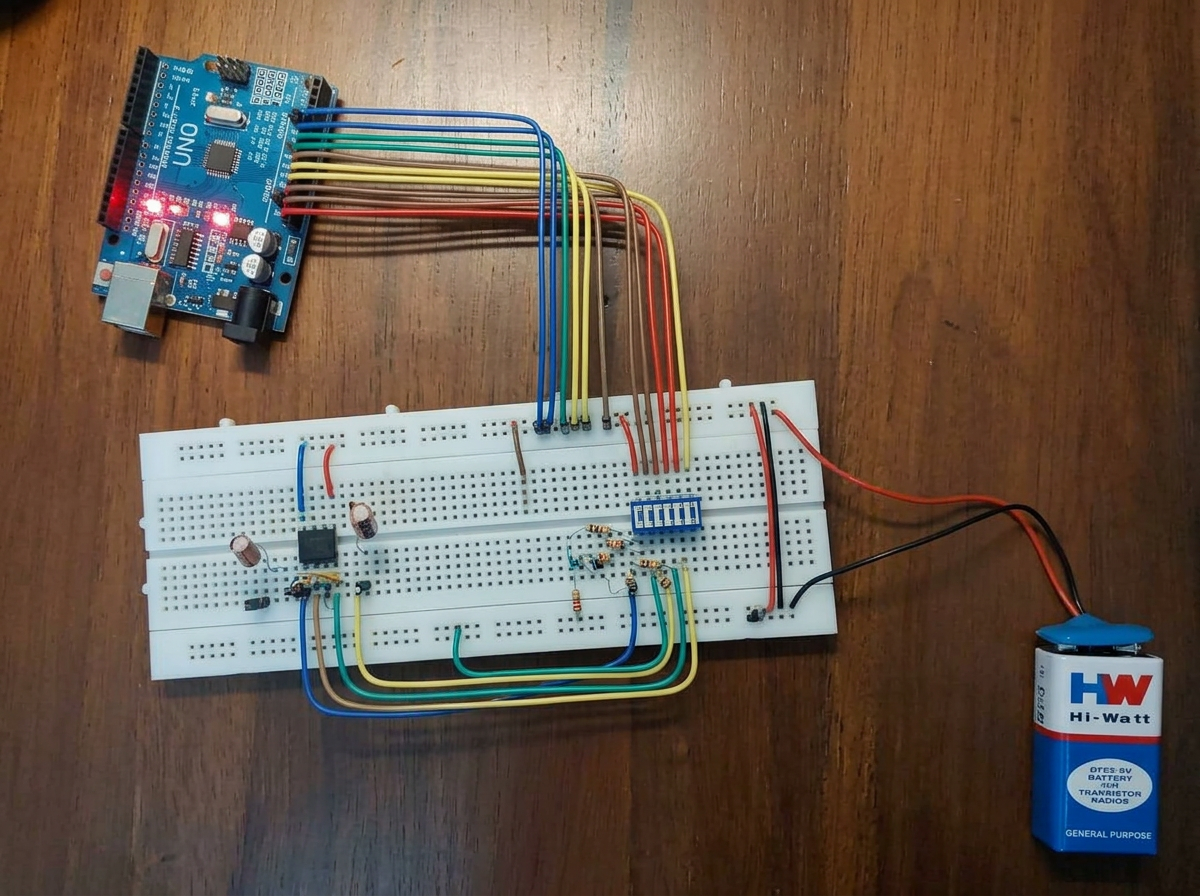
Project Overview
A 4-bit digital-to-analog converter built from an R-2R resistor ladder driven by an Arduino. Sweeps through all 16 binary combinations and produces evenly spaced analog voltage steps that were verified with a multimeter and scope.
Understand DAC fundamentals — resolution, monotonicity, linearity — by building one from discrete components rather than using an on-chip peripheral.
- ›Design an R-2R ladder network with matched resistors
- ›Drive the ladder from four GPIO pins in sequence
- ›Verify 16 discrete output levels with lab instrumentation
- ›Document non-idealities: source impedance, GPIO voltage drop
System Architecture
Four GPIO outputs feed an R-2R ladder whose Thevenin equivalent produces V_out = V_ref × N / 16. A small buffer stage isolates the ladder from downstream load.
Each GPIO contributes a weighted current into the ladder node. Summed via superposition, the node voltage encodes the 4-bit input as a fraction of V_ref.
Hardware Components
- ▹Arduino Uno
- ▹Precision 1% resistors (R and 2R pairs)
- ▹Breadboard + jumper wires
- ▹Digital multimeter, oscilloscope
Software Stack
- ▹Arduino IDE sketch cycling 0..15 on 4 GPIOs
Development Journey
Built the ladder on breadboard, characterised the output against theory, then documented deviations caused by GPIO drive strength and resistor tolerance.
R-2R uses only two resistor values → far easier to match and scales cleanly with resolution.
Challenges & Solutions
Traced to GPIO logic-low not being a true 0 V. Documented as a source-impedance effect rather than a design bug.
Performance Results
Visuals & Media
Downloads
Improvements & Lessons
- +Extend to 8-bit ladder for smoother output
- +Add an op-amp output buffer with low output impedance
- +Migrate the ladder to a proper PCB in Altium
- ›GPIO voltage is not an ideal 0/3.3 V — real-world DACs must account for source impedance.
- ›Component tolerance directly limits DAC linearity.